I. Reasons for Fuel Tank Replacement in Diesel Generator Sets
- Structural Damage: Corrosion perforation (common in carbon steel tanks over five years old) or weld seam cracking.
- Excessive Contamination: Sediment exceeding 5% of the tank height or microbial content > 10³ CFU/mL.
- Capacity Upgrade: Insufficient original tank capacity (e.g., upgrading from 200L to 500L).
- Regulatory Changes: New EPA Tier 4 standards require double-walled, leak-proof tanks.
Case Study: A coastal factory experienced a 2mm leak at the bottom of the tank due to salt spray corrosion, resulting in a loss of approximately 30 liters of diesel per month. The replacement saved over $5,000 annually.
II. Core Preparations Before Operation
1. Safety Precautions (OSHA Standards)
- Ventilation: Use an explosion-proof fan to maintain airflow (≥0.5 m/s).
- Static Protection: Wear conductive shoes (resistance of 1×10⁵ to 1×10⁸ Ω) and grounding cables (≥16mm² cross-sectional area).
- Fuel Handling: Prepare Class II explosion-proof containers (≥110% of the tank capacity).
2. Tool List
| Tool Type | Specification Requirements |
|---|---|
| Fuel Pump | Explosion-proof, ≥50L/min flow rate |
| Pipe Cutter | Suitable for DN25~DN50 metal pipes |
| Combustible Gas Detector | Range: 0-100% LEL, Accuracy: ±3% |
| Torque Wrench | Range: 20-150 N·m, with scale display |
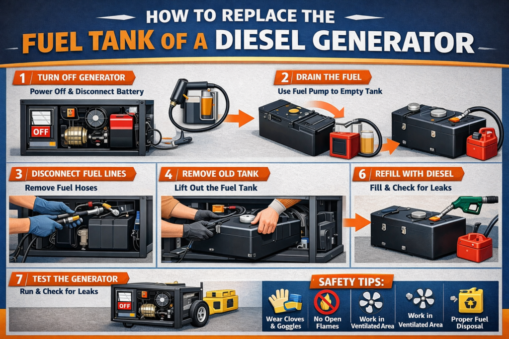
III. Step-by-Step Procedure (Using a 500L Steel Tank as an Example)
Stage 1: System Drainage
- Fuel Transfer:
- Use the fuel pump to extract residual fuel (retain 5cm of fuel to prevent pump dry-running).
- Add fuel stabilizer (e.g., STA-BIL 22240) to prevent diesel degradation.
- Pipeline Handling:
- Install a shut-off valve (ASME B16.34 standard) 30cm from the inlet/return line.
- Purge the pipeline with nitrogen for 3 minutes (pressure ≤ 0.2 MPa).
Stage 2: Removing the Old Tank
- Dismantling:
- Remove anchor bolts (M16×120, typically requiring 120 N·m torque).
- Use cold-cutting methods (e.g., water jet or grinding wheel saw) to cut welded joints.
- Pollution Control:
- Use absorbent pads to collect dripping fuel (absorption capacity ≥20 times its weight).
- Dispose of the old tank according to EPA 40 CFR Part 261 standards.
Stage 3: Installing the New Tank
- Positioning and Calibration:
- Use a laser level to ensure tank tilt <1° (to avoid fuel gauge errors).
- Place a 6mm neoprene rubber vibration pad (Shore hardness 70±5) at the base.
- Pipeline Connection:
- Use DN40 stainless steel corrugated pipes (bend radius ≥8 times the diameter).
- Install the breather valve 15cm above the maximum liquid level (API 2000 standard).
Key Data:
- Flange bolt tightening sequence: Cross-pattern in three stages (30%/70%/100%).
- Sealant: Permatex 51813 (temperature resistance: -54°C to 204°C).
IV. Testing and Acceptance Standards
1. Pressure Testing
- Water Pressure Test: Gradually pressurize to 0.035 MPa and hold for 30 minutes (pressure drop <5% is acceptable).
- Vacuum Test: Draw to -0.007 MPa and maintain for 15 minutes (industrial tanks allow ≤3mL/h leakage rate).
2. Functional Verification
- Simulated Full Load Operation: Continuous rated power output for 2 hours, monitor fuel line temperature (<55°C is normal).
- Fuel Transmission Test: Pressure drop from the tank to the engine should be <10 kPa.
Case Study: After replacing the fuel tank at a data center, the fuel flow increased from 82 L/min to 95 L/min, reducing generator startup time by 0.8 seconds.
V. Common Problem-Solving Solutions
Problem 1: Pipe Vibration Noise
- Cause: Excessive clamp spacing (should be ≤1.5 times the pipe diameter).
- Solution: Install a hydraulic pulse damper (e.g., Haldex 260002).
Problem 2: Fuel Level Sensor Misreporting
- Calibration Method:
- Adjust the zero-point potentiometer to 4mA output when empty.
- Adjust the range potentiometer to 20mA output when full.
Problem 3: Microbial Contamination Recurrence
- Prevention Strategy:
- Add Biobor JF biocide monthly (concentration >200 ppm).
- Install a coalescing filter (separation efficiency >95%).
VI. Innovative Technological Applications
1. Smart Monitoring System
- Embedded Corrosion Sensors (e.g., RCS-MINI): Real-time monitoring of tank wall thickness.
- Ultrasonic Level Sensor: Accuracy of ±1mm with temperature compensation.
2. Modular Quick-Install Tank
- Quick-Connect Fittings (APM Hexseal design): Reduces replacement time by 60%.
- Teflon Coating Liner: Extends service life to 15 years.