When installing a diesel generator, most people focus on the engine, alternator, and control system. However, the diesel generator exhaust pipe installation is just as important. A poorly designed exhaust system can cause excessive engine back pressure, overheating, noise problems, and even safety risks due to exhaust gas accumulation.
A properly installed diesel generator exhaust system ensures that hot exhaust gases are safely discharged outside the building while maintaining optimal generator performance. In industrial applications such as factories, construction sites, and backup power systems, correct exhaust pipe installation is considered a standard engineering requirement.
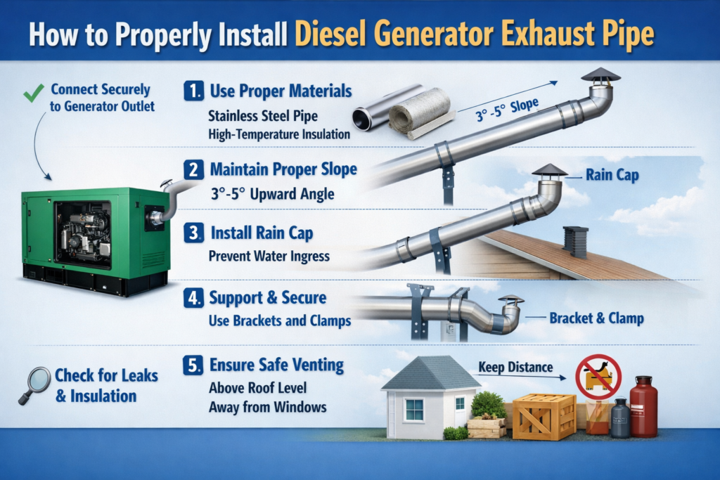
This guide explains the practical steps and key considerations for installing a diesel generator exhaust pipe system.
Why Diesel Generator Exhaust Pipe Installation Is Important
The exhaust system of a generator is responsible for directing combustion gases away from the engine and the installation area. If the exhaust pipe design is incorrect, the generator may experience higher fuel consumption, reduced efficiency, and increased maintenance issues.
A well-designed diesel generator exhaust pipe system helps to:
- Maintain proper engine airflow and reduce back pressure
- Improve overall generator efficiency
- Reduce operating noise through proper muffler installation
- Prevent dangerous exhaust gas accumulation
- Extend the service life of the diesel engine
For well-known generator brands such as Cummins, Perkins, Weichai, MTU, and Volvo, manufacturers usually provide recommended exhaust pipe specifications that should be followed during installation.
Main Components of a Diesel Generator Exhaust System
Before starting installation, it is useful to understand the main parts of a typical diesel generator exhaust system.
The system usually includes:
- Exhaust outlet from the engine
- Flexible exhaust connector
- Exhaust muffler or silencer
- Steel exhaust pipe
- Pipe supports and brackets
- Thermal insulation layer
- Outdoor exhaust outlet or rain cap
Among these components, the flexible exhaust pipe for diesel generators is particularly important. It absorbs vibration from the engine and prevents stress on the main exhaust piping.
Step-by-Step Guide to Installing a Diesel Generator Exhaust Pipe
Proper installation requires careful planning of the pipe layout, diameter, and support structure. The following steps are commonly used in industrial diesel generator exhaust installations.
Select the Correct Exhaust Pipe Diameter
Choosing the correct pipe diameter is the first step in designing a reliable diesel generator exhaust pipe system.
If the pipe diameter is too small, exhaust flow becomes restricted, which increases engine back pressure. Excessive back pressure can reduce engine power and increase fuel consumption.
As a general reference:
- 100KW diesel generator: about 100–125 mm exhaust pipe
- 200KW diesel generator: about 125–150 mm exhaust pipe
- 500KW diesel generator: about 200 mm or larger
However, the final diesel generator exhaust pipe size should always follow the generator manufacturer’s recommendations.
Install a Flexible Exhaust Connector
A flexible exhaust connector should always be installed between the generator engine and the rigid exhaust pipe.
This component serves several purposes:
- Absorbs engine vibration
- Prevents damage to the exhaust piping
- Reduces mechanical stress on the turbocharger
Without a flexible connector, vibration from the engine can eventually crack the exhaust pipe or loosen pipe joints.
Install a Diesel Generator Muffler
Most diesel generators require an exhaust muffler to control noise levels. The diesel generator exhaust muffler is usually installed along the exhaust pipe line, either inside the generator room or outside the building.
Different muffler types are available depending on noise reduction requirements:
- Industrial grade mufflers
- Residential grade silencers
- Critical grade silencers for hospitals or data centers
Proper muffler installation is essential for reducing the noise level of diesel generators used in urban or commercial environments.
Ensure Proper Pipe Slope and Drainage
When installing the exhaust pipe, it is recommended to maintain a slight downward slope away from the generator.
This prevents rainwater or condensation from flowing back toward the engine. In many professional installations, a small drain valve is installed at the lowest point of the pipe to remove condensation.
Proper drainage is an important detail in diesel generator exhaust pipe installation, especially in humid environments.
Apply Exhaust Pipe Insulation
Diesel generator exhaust pipes operate at very high temperatures. In many cases, exhaust gas temperatures can exceed 400°C to 600°C.
For safety and temperature control, the exhaust pipe should be covered with high-temperature insulation materials, such as:
- Fiberglass insulation wrap
- Aluminum-clad insulation
- High-temperature exhaust blankets
Good diesel generator exhaust insulation helps reduce heat inside the generator room and improves operator safety.
Install the Outdoor Exhaust Outlet
The final section of the exhaust pipe should lead outside the building. The outlet should be positioned so that exhaust gases are safely dispersed into the atmosphere.
Common installation practices include:
- Directing the exhaust away from doors and windows
- Installing a rain cap to prevent water entry
- Ensuring sufficient height above ground level
A properly positioned diesel generator exhaust outlet improves safety and prevents exhaust gases from re-entering the building.
Common Problems in Diesel Generator Exhaust Installation
In practice, several common mistakes often occur when installing a diesel generator exhaust system.
Some of the most frequent issues include:
Excessive pipe bends
Too many elbows increase exhaust resistance and reduce airflow.
Insufficient pipe supports
Long exhaust pipes must be properly supported to prevent sagging.
Improper pipe diameter
Using pipes that are too small increases engine back pressure.
Lack of insulation
Uninsulated pipes increase the temperature inside the generator room.
Avoiding these mistakes helps ensure reliable long-term operation of the generator.
Routine Maintenance of Diesel Generator Exhaust Pipes
Even after installation, the exhaust system should be inspected regularly as part of generator maintenance.
Recommended checks include:
- Inspecting pipe connections for leaks
- Checking the condition of insulation materials
- Removing soot buildup inside the muffler
- Ensuring rain caps and drains are functioning properly
Regular inspection helps maintain the safety and efficiency of the diesel generator exhaust pipe system.
FAQ About Diesel Generator Exhaust Pipe Installation
How long can a diesel generator exhaust pipe be?
The total length of the exhaust pipe should be limited to avoid excessive back pressure. In most installations, engineers try to keep the pipe as short and straight as possible.
Does a diesel generator need a muffler?
Yes. Most diesel generators use a muffler or silencer to reduce noise levels, especially in residential or commercial areas.
Why is insulation required on exhaust pipes?
Exhaust pipes operate at very high temperatures. Insulation reduces heat radiation and protects personnel working near the generator.
Can multiple generators share one exhaust pipe?
Generally, each generator should have its own dedicated exhaust pipe to prevent pressure interference between units.
Conclusion
Proper diesel generator exhaust pipe installation is essential for safe and efficient generator operation. By selecting the correct pipe size, installing flexible connectors and mufflers, ensuring proper drainage, and applying insulation, the exhaust system can operate reliably for many years.
Whether the generator is used in factories, construction sites, hospitals, or backup power systems, a well-designed diesel generator exhaust system plays a key role in maintaining performance and safety.